Variable Clock v4
$22.00 Sold out

The most advanced version on the "Variable Clock" family!
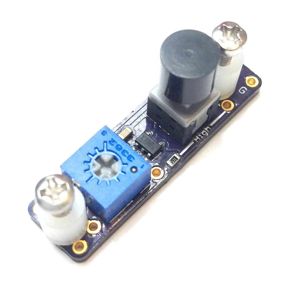
This is a variable clock output device.
You can manipulate the speed of the Game Boy processor on the fly with a potentiometer.
The pitch of the sound will become lower as you slow it down and it will become higher when you speed it up.
You can make some incredible sounds with this kit as well as adding a whole new way to play games!
Built in features:
-On/off push button switch:
No need to get a separate switch for this kit. It is built right into the PCB!
-Panel mounting:
This kit should be mounted directly the Game Boy case with the provided screws and spacer.
-High limiter:
This will limit how fast it will go. Many devices will crash if pushed too far.
A 10K SMD resistor is pre-soldered for installation into an Original Game Boy(DMG) or Game Boy Pocket(MGB).
It can easily be removed with a razor blade and you may install a different through hole resistor(an 8K resistor is ideal for the Game Boy Color(CGB).
You can purchase this as:
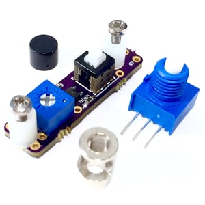
-"Basic kit" supply your own wire, switch, potentiometer and knob.
-"Full kit" includes a micro potentiometer, 1/8" to 1/4" potentiometer shaft adapter and enough wire to install it into a Game Boy. *no knob is included so that you can choose any kind of knob on the shop*
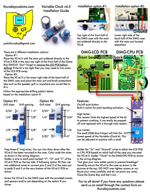
Installation instructions are in the last picture.
Save the image for higher quality.
For installation into a Super Game Boy cartridge for SNES follow this wiring diagram.


